Modular construction in Canada and the U.S. consists mainly of wood structural components prefabricated offsite in a manufacturing facility. These components are then transported and assembled onsite. Since both offsite and onsite work occur simultaneously, opportunities exist to shorten construction schedules and accelerate income generation, particularly for projects with repetitive building units such as apartments and hotels. Modular construction may also reduce job costs while improving building performance and housing affordability.
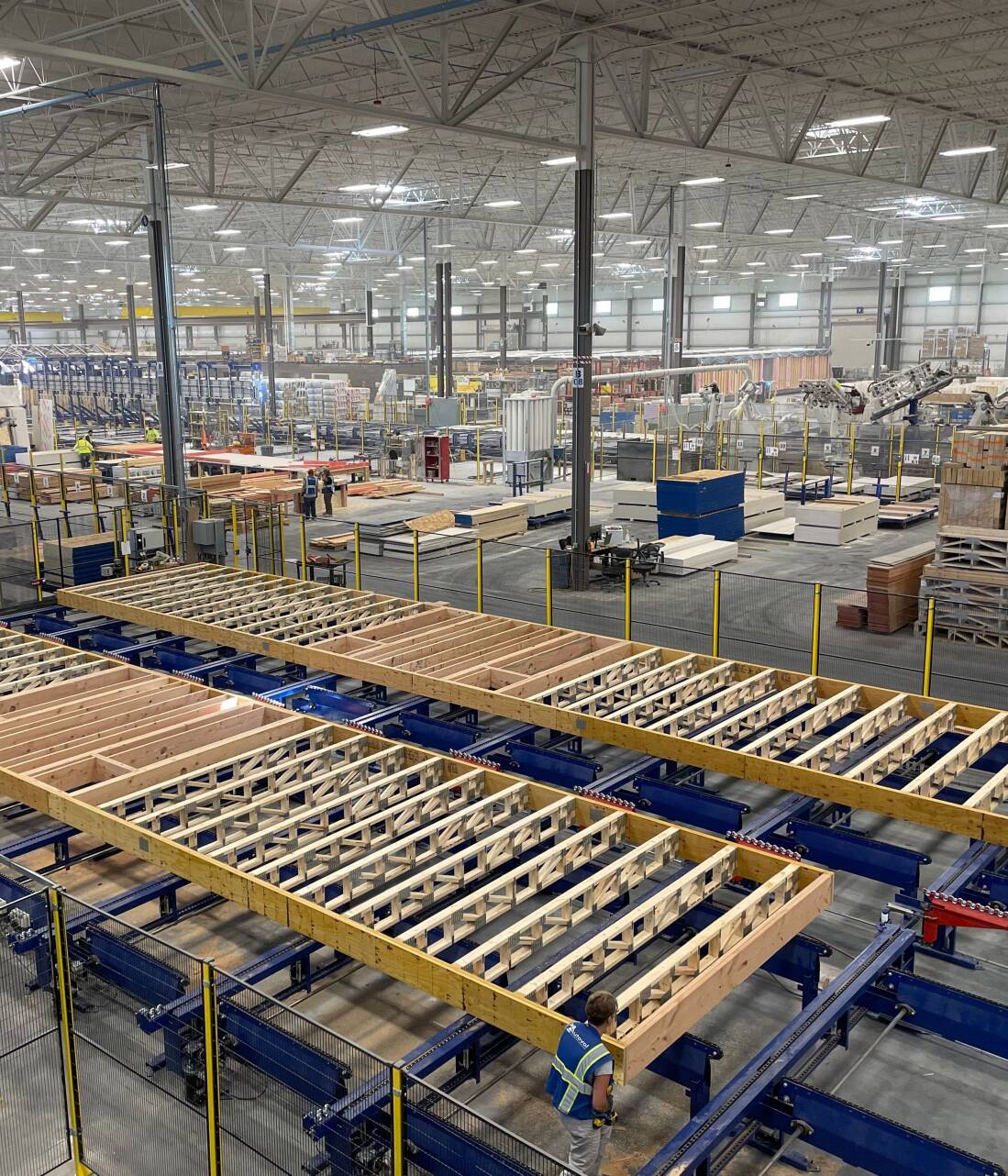
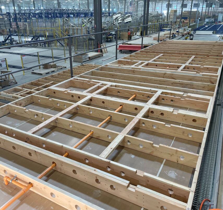
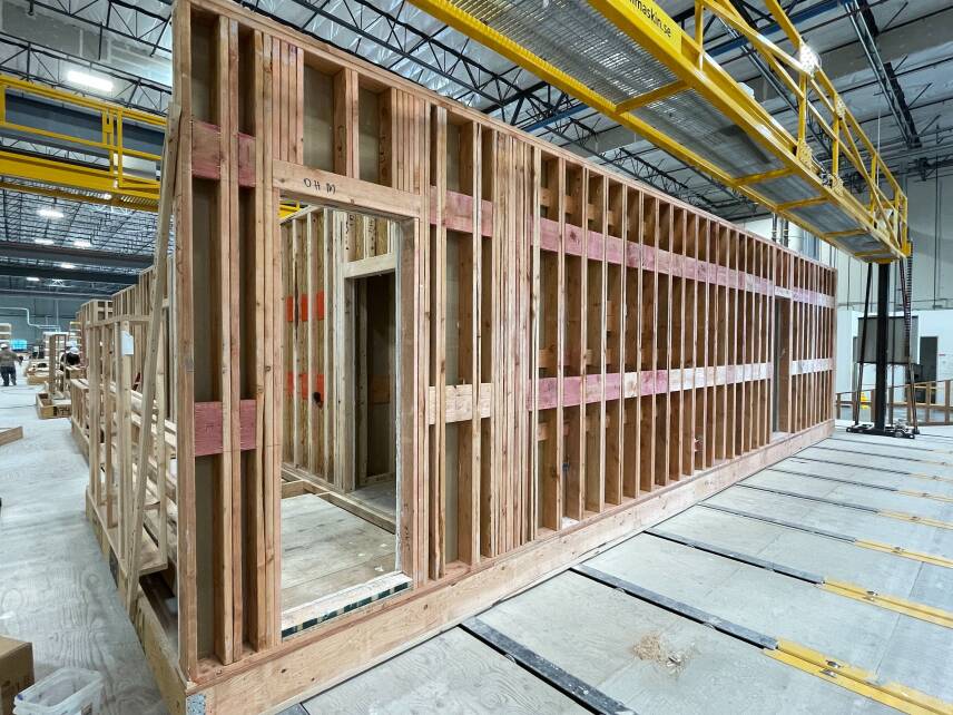
Volumetric modular units are prefabricated with floors, walls and ceilings in the factory (Figure 1). Framing is unavoidably doubled between modules when placed onsite (Figure 2). While this may result in added materials and cost, it may also result in buildings more resistant to wind, seismic and fire hazards. This is particularly important given that most modular construction serves vulnerable populations living in affordable housing. Buildings that are more resilient to natural disasters may also have a longer service life, require less maintenance and have a smaller carbon footprint. Together, these factors may reduce insurance premiums and other operational costs.
Background
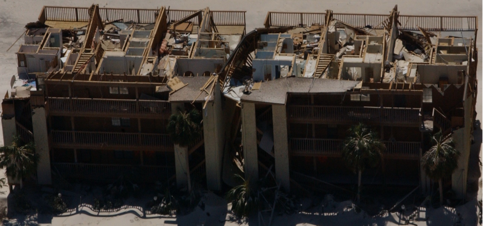
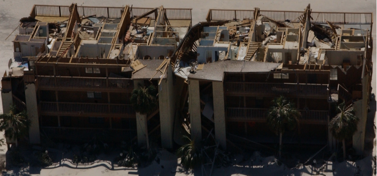
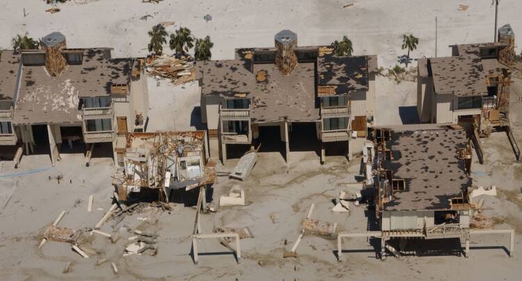
Intuitively, modular components produced in a factory-controlled setting should have higher levels of quality control and better precision of joints and connections. In 1993, FEMA published Building Performance: Hurricane Andrew in Florida, evaluating the performance of modular buildings following a 265k/h (165m/h) Category 5 windstorm event that damaged or destroyed 187,500 residential structures. According to FEMA, the module-to-module combination of the units appeared to provide an inherently rigid system that performed better than conventional site-built framing. Other studies have shown that modular buildings have higher levels of deflection control and were better able to resist wind-induced strain energy, particularly in multi-story buildings. Overall, modular buildings typically have more symmetric, compartmentalized geometries that are better able to uniformly distribute wind loads and minimize localized areas of weakness when compared to site-built multifamily buildings (Figure 3).

FEATURE
Hazard Resilience of Modular Construction
Scroll to Read
Methods
In 2024, researchers at the University of Nebraska-Lincoln performed a design review of modular buildings from a recently published U.S. Department of Energy (USDOE) field study ‘Modular Multifamily Construction’. Data was collected from 12 modular multifamily buildings completed between 2021 and 2023 in Los Angeles (3), San Francisco (4), Philadelphia (3) and Seattle (2). Modular buildings averaged 6 stories in height, 13,000m2 (140,000ft2) of floor area and 130 dwelling units per building. Modules for the 12 modular multifamily buildings were manufactured by a total of six different North American manufacturers.
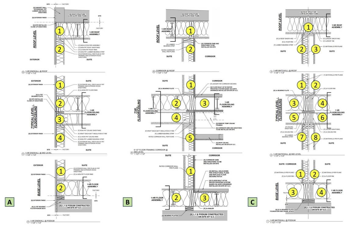
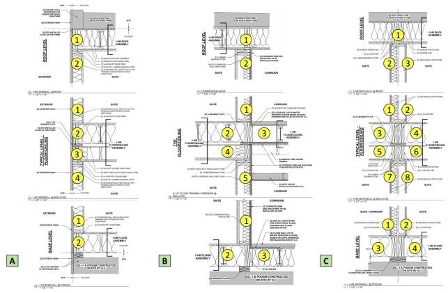
The design review identified applicable building codes, design wind speeds, structural framing and structural connections for each building. Specifically, data included floor, wall, ceiling and roof framing for exterior end and side walls, interior corridor walls and interior mate-line walls between modules (Figure 4). Design loads for dwelling units, roof decks, corridors and commons spaces were documented as were window-to-wall ratios and other related envelope data.
Wood Floor Framing
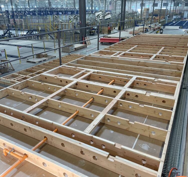
Floor framing data for modular buildings in this study included end-wall rim boards, side-wall rim boards, floor joists and floor decking for both dwelling units and corridors. Common end-wall rim board configurations included doubled 5x30cm (2x12in) nominal dimensional lumber whereas side-wall rim board configurations included 30cm (12in) laminated veneer lumber (LVL). Common floor joist configurations included a combination of 5x30cm (2x12in) dimensional lumber spaced 40cm (16in) on-center (o.c.) and 30cm (12in) pre-engineered open-web floor trusses spaced 60cm (24in) o.c. (Figure 5). Floor joists were doubled at corridor wall locations and either side of shaft wall locations. The most common floor decking configuration was 2cm (¾in) tongue-and-groove (T&G) plywood both glued and nailed 15cm (6in) o.c. to floor framing.


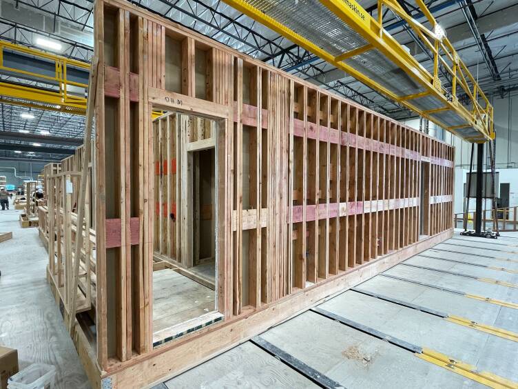
An evaluation of wall framing included exterior end and side wall framing, mate-line wall framing and corridor wall framing at base level, mid-level and roof level. The most common exterior end wall, side wall and corridor framing configuration was 5x15cm (2x6in) nominal dimensional lumber. The most common mate-line wall framing configuration was 5x10cm (2x4in) dimensional lumber. Framing at base level most commonly consisted of doubled studs 30cm (12in) o.c. (Figure 6) whereas framing at mid-level and roof levels most commonly consisted of single studs 30cm (12in) o.c. or 40cm (16in) o.c. Timber posts, LVL posts and (or) stud packs were placed at bearing points throughout the wall assembly, usually at module corners and corridor-mate-line wall locations. The most common wall sheathing configuration for exterior end and side wall framing, mate-line wall framing and corridor wall framing at base level, mid-level and roof level was 1.25cm (½in) oriented strand board (OSB) or plywood nailed 15cm (6in) o.c. to wall framing. Continuous floor-to-ceiling wall sheathing provides diaphragms or shear walls at nearly all exterior end and side walls, mate-line walls and corridor walls.
Wood Wall Framing

Ceiling and roof framing data for modular buildings in this study included end-wall rim boards, side-wall rim boards and ceiling joists for both dwelling units and corridors. Common ceiling end-wall rim board configurations included doubled 5x20cm (2x8in) nominal dimensional lumber whereas side-wall rim board configurations included 20cm (8in) LVL. Common ceiling joist configurations included 5x20cm (2x8in) dimensional lumber spaced 60cm (24in) o.c. (Figure 7). Ceiling joists were often doubled at corridor wall locations and either side of shaft wall locations. Ceiling framing often included 1.25cm (½in) OSB or plywood nailed 15cm (6in) o.c. to ceiling joists with one or two layers of 1.5cm (5/8in) Type X gypsum board placed over the sheathing. Ceiling framing in the corridor was temporary and removed once the modular unit was set to accommodate onsite installation of MEP systems.
Similarly, common roof end-wall rim board configurations included doubled 5x30cm (2x12in) nominal dimensional lumber whereas side-wall rim board configurations included 30cm (12in) LVL. Common roof rafter configurations included 5x30cm (2x12in) dimensional lumber or wood I-joist spaced 40cm (16in) o.c., or, 30cm (12in) pre-engineered roof trusses spaced 60cm (24in) o.c. The most common roof decking configuration was 1.5cm (5/8in) plywood nailed 15cm (6in) o.c. to roof framing.
Wood Ceiling and Roof Framing
Figure 5
Figure 7
Figure 6
Figure 4
Figure 3

Results
Design wind speeds for modular buildings in this study ranged from 150-185k/h (95-115m/h). Gravity load design conditions were similar for all buildings and included 100kg/m2 (20psf) roof load, 200kg/m2 (40psf) dwelling unit load and 500kg/m2 (100psf) corridor load. Window-to-wall ratios averaged 20% per building. Four modular buildings were slab-on-grade (SOG) with Type-III modular wood framing. The remaining 8 modular buildings were Type III modular wood framing over 1-4 stories of Type I concrete and (or) steel podium.
Summary
As shown, the methods and materials used in modular multifamily construction are similar to those used in site-built construction. Observed differences include ‘doubled’ ceiling-floor framing between modular units necessary to maintain structural integrity during transport and crane placement and for factory installation of ceiling MEP and finish systems. Other observed differences include nearly continuous structural sheathing for all exterior end and side walls, mate-line walls and corridor walls. While much of this sheathing is again necessary to maintain structural integrity during transport and crane placement, it nevertheless creates increased shear wall resistance to lateral loads beyond that normally found in site-built construction or required by building codes.
Related, the relatively short spans of modular floor, ceiling and roof assemblies combined with symmetric, compartmentalized geometries creates a more rigid system better able to uniformly distribute lateral wind and seismic loads. By comparison, there is usually greater geometric variability in site-built construction and less structural uniformity. As a result, site-built construction is more prone to uneven load distribution and areas of localized weakness, leading to progressive failure of structures under load.
Figure 1

FEATURE
Hazard Resilience of Modular Construction
Modular construction in Canada and the U.S. consists mainly of wood structural components prefabricated offsite in a manufacturing facility. These components are then transported and assembled onsite. Since both offsite and onsite work occur simultaneously, opportunities exist to shorten construction schedules and accelerate income generation, particularly for projects with repetitive building units such as apartments and hotels. Modular construction may also reduce job costs while improving building performance and housing affordability.
Volumetric modular units are prefabricated with floors, walls and ceilings in the factory (Figure 1). Framing is unavoidably doubled between modules when placed onsite (Figure 2). While this may result in added materials and cost, it may also result in buildings more resistant to wind, seismic and fire hazards. This is particularly important given that most modular construction serves vulnerable populations living in affordable housing. Buildings that are more resilient to natural disasters may also have a longer service life, require less maintenance and have a smaller carbon footprint. Together, these factors may reduce insurance premiums and other operational costs.
Background
Intuitively, modular components produced in a factory-controlled setting should have higher levels of quality control and better precision of joints and connections. In 1993, FEMA published Building Performance: Hurricane Andrew in Florida, evaluating the performance of modular buildings following a 265k/h (165m/h) Category 5 windstorm event that damaged or destroyed 187,500 residential structures. According to FEMA, the module-to-module combination of the units appeared to provide an inherently rigid system that performed better than conventional site-built framing. Other studies have shown that modular buildings have higher levels of deflection control and were better able to resist wind-induced strain energy, particularly in multi-story buildings. Overall, modular buildings typically have more symmetric, compartmentalized geometries that are better able to uniformly distribute wind loads and minimize localized areas of weakness when compared to site-built multifamily buildings (Figure 3).
Methods
In 2024, researchers at the University of Nebraska-Lincoln performed a design review of modular buildings from a recently published U.S. Department of Energy (USDOE) field study ‘Modular Multifamily Construction’. Data was collected from 12 modular multifamily buildings completed between 2021 and 2023 in Los Angeles (3), San Francisco (4), Philadelphia (3) and Seattle (2). Modular buildings averaged 6 stories in height, 13,000m2 (140,000ft2) of floor area and 130 dwelling units per building. Modules for the 12 modular multifamily buildings were manufactured by a total of six different North American manufacturers.
The design review identified applicable building codes, design wind speeds, structural framing and structural connections for each building. Specifically, data included floor, wall, ceiling and roof framing for exterior end and side walls, interior corridor walls and interior mate-line walls between modules (Figure 4). Design loads for dwelling units, roof decks, corridors and commons spaces were documented as were window-to-wall ratios and other related envelope data.
Results
Design wind speeds for modular buildings in this study ranged from 150-185k/h (95-115m/h). Gravity load design conditions were similar for all buildings and included 100kg/m2 (20psf) roof load, 200kg/m2 (40psf) dwelling unit load and 500kg/m2 (100psf) corridor load. Window-to-wall ratios averaged 20% per building. Four modular buildings were slab-on-grade (SOG) with Type-III modular wood framing. The remaining 8 modular buildings were Type III modular wood framing over 1-4 stories of Type I concrete and (or) steel podium.
Figure 4
Figure 1
Wood Floor Framing
Floor framing data for modular buildings in this study included end-wall rim boards, side-wall rim boards, floor joists and floor decking for both dwelling units and corridors. Common end-wall rim board configurations included doubled 5x30cm (2x12in) nominal dimensional lumber whereas side-wall rim board configurations included 30cm (12in) laminated veneer lumber (LVL). Common floor joist configurations included a combination of 5x30cm (2x12in) dimensional lumber spaced 40cm (16in) on-center (o.c.) and 30cm (12in) pre-engineered open-web floor trusses spaced 60cm (24in) o.c. (Figure 5). Floor joists were doubled at corridor wall locations and either side of shaft wall locations. The most common floor decking configuration was 2cm (¾in) tongue-and-groove (T&G) plywood both glued and nailed 15cm (6in) o.c. to floor framing.
Figure 5

Summary
As shown, the methods and materials used in modular multifamily construction are similar to those used in site-built construction. Observed differences include ‘doubled’ ceiling-floor framing between modular units necessary to maintain structural integrity during transport and crane placement and for factory installation of ceiling MEP and finish systems. Other observed differences include nearly continuous structural sheathing for all exterior end and side walls, mate-line walls and corridor walls. While much of this sheathing is again necessary to maintain structural integrity during transport and crane placement, it nevertheless creates increased shear wall resistance to lateral loads beyond that normally found in site-built construction or required by building codes.
Related, the relatively short spans of modular floor, ceiling and roof assemblies combined with symmetric, compartmentalized geometries creates a more rigid system better able to uniformly distribute lateral wind and seismic loads. By comparison, there is usually greater geometric variability in site-built construction and less structural uniformity. As a result, site-built construction is more prone to uneven load distribution and areas of localized weakness, leading to progressive failure of structures under load.
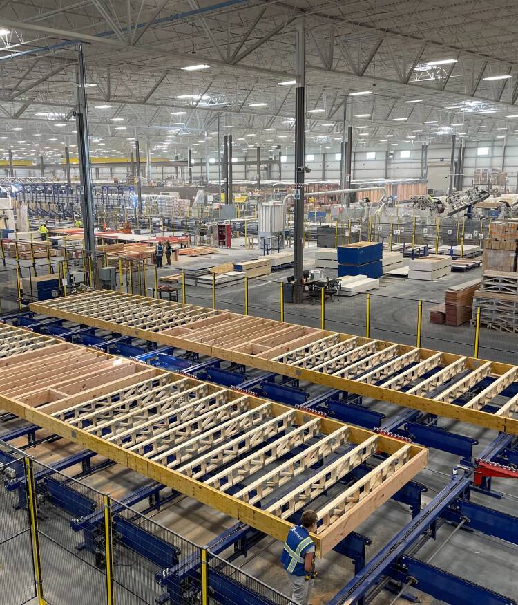
Figure 7

Ceiling and roof framing data for modular buildings in this study included end-wall rim boards, side-wall rim boards and ceiling joists for both dwelling units and corridors. Common ceiling end-wall rim board configurations included doubled 5x20cm (2x8in) nominal dimensional lumber whereas side-wall rim board configurations included 20cm (8in) LVL. Common ceiling joist configurations included 5x20cm (2x8in) dimensional lumber spaced 60cm (24in) o.c. (Figure 7). Ceiling joists were often doubled at corridor wall locations and either side of shaft wall locations. Ceiling framing often included 1.25cm (½in) OSB or plywood nailed 15cm (6in) o.c. to ceiling joists with one or two layers of 1.5cm (5/8in) Type X gypsum board placed over the sheathing. Ceiling framing in the corridor was temporary and removed once the modular unit was set to accommodate onsite installation of MEP systems.
Similarly, common roof end-wall rim board configurations included doubled 5x30cm (2x12in) nominal dimensional lumber whereas side-wall rim board configurations included 30cm (12in) LVL. Common roof rafter configurations included 5x30cm (2x12in) dimensional lumber or wood I-joist spaced 40cm (16in) o.c., or, 30cm (12in) pre-engineered roof trusses spaced 60cm (24in) o.c. The most common roof decking configuration was 1.5cm (5/8in) plywood nailed 15cm (6in) o.c. to roof framing.
Wood Ceiling and Roof Framing
Figure 6

An evaluation of wall framing included exterior end and side wall framing, mate-line wall framing and corridor wall framing at base level, mid-level and roof level. The most common exterior end wall, side wall and corridor framing configuration was 5x15cm (2x6in) nominal dimensional lumber. The most common mate-line wall framing configuration was 5x10cm (2x4in) dimensional lumber. Framing at base level most commonly consisted of doubled studs 30cm (12in) o.c. (Figure 6) whereas framing at mid-level and roof levels most commonly consisted of single studs 30cm (12in) o.c. or 40cm (16in) o.c. Timber posts, LVL posts and (or) stud packs were placed at bearing points throughout the wall assembly, usually at module corners and corridor-mate-line wall locations. The most common wall sheathing configuration for exterior end and side wall framing, mate-line wall framing and corridor wall framing at base level, mid-level and roof level was 1.25cm (½in) oriented strand board (OSB) or plywood nailed 15cm (6in) o.c. to wall framing. Continuous floor-to-ceiling wall sheathing provides diaphragms or shear walls at nearly all exterior end and side walls, mate-line walls and corridor walls.
Wood Wall Framing
Figure 3
