Project Overview
Pathway Non-Profit Housing is an interfaith non-profit corporation that owns and operates two apartment buildings built in the early 1990s. By expanding their existing Arbour Mill property in Mississauga, they avoided the challenge of finding new land and were able to welcome new residents into an established, supportive community.
The resulting two-storey, 10m x 18m vertical addition at the north end of the building connects to the fifth and sixth floors of the adjacent seven-storey block, creating a cohesive addition without disrupting the building’s layout. Because the building remained occupied throughout, reducing construction time was a priority, a requirement that supported the choice of mass timber.
article en vedette
Vertical Addition Adds Essential Housing Units
Faites défiler
pour lire

PROJECT TEAM:
Regional Municipality of Peel
Rapid Housing Initiative
Pathway Non-Profit Community Developments Inc. of Peel (Pathway)
GSAI Planners
Tafler Rylett Architects
Engineering Link (Structural)
GPY & Associates Engineering Inc. (Mechanical)
Summit Engineering (Electrical)
Disano Sprinklers
Vortex Fire
HGC Acoustic Consultants
RDH Building Science
Scott Construction
Element5
Photos: Scott Construction Group, Derek Szczerbowski , CWC
Project Benefits
Sustainable Local Procurement: The CLT panels were fabricated at Element5’s FSC-certified facility in St. Thomas using wood sourced from sustainably managed Ontario forests, ensuring responsible practices from harvest to production.
Low-Carbon Construction: Using mass timber instead of steel reduced the structure’s embodied carbon by an estimated 20–50%. Its proximity to the manufacturing facility minimized transportation-related emissions and costs.
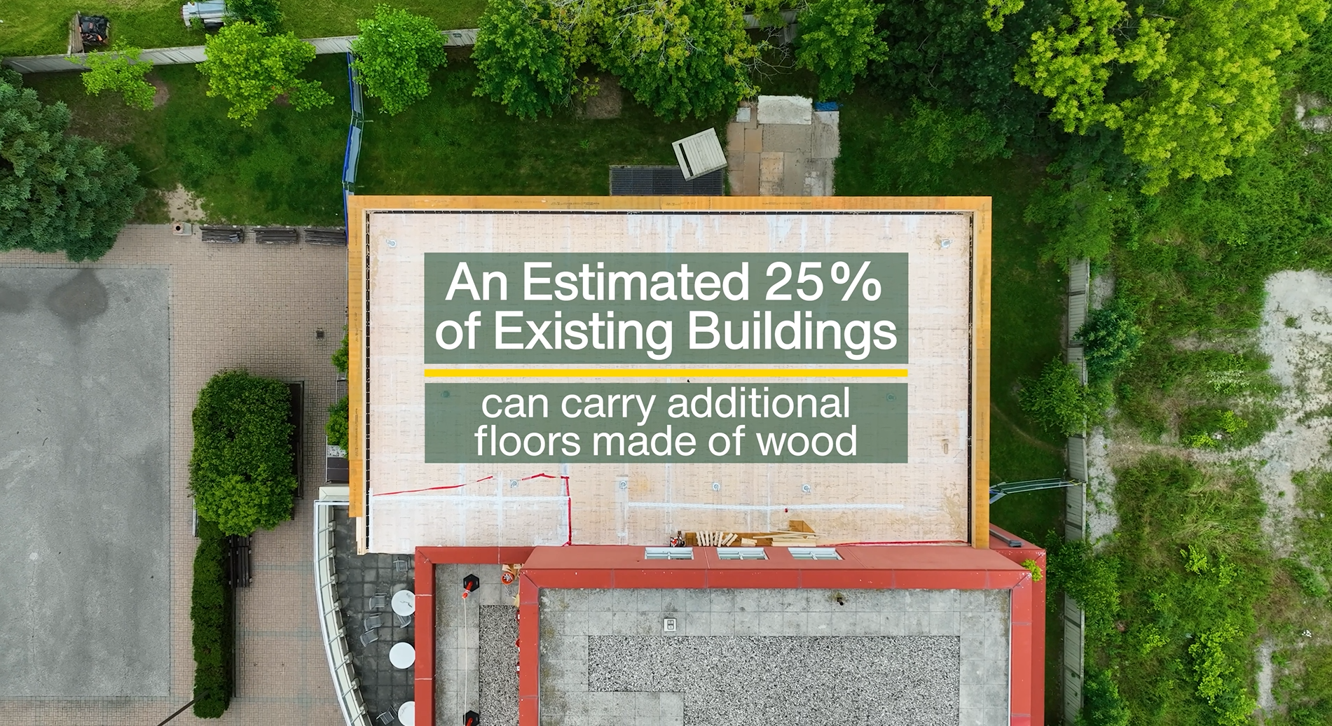
Lightweight Structural System: With a structural weight roughly 50% lower than an equivalent concrete building, the mass timber addition could be supported by the existing structure without the need for reinforcement.
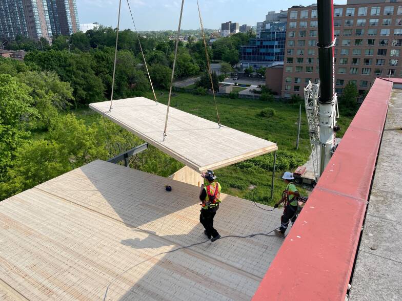
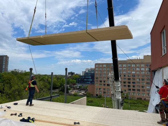
Cost-Effective, Rapid Construction: Mass timber construction is efficient and fast to assemble—typically 25% quicker than conventional methods, and in some cases even faster. For Pathway, close coordination of fabrication, delivery, and installation enabled the entire structure to be erected in just two and a half weeks. Full-length CLT floor panels and on-site drilling of mechanical penetrations further accelerated construction.
Quieter, Less Disruptive Site: Mass timber buildings are assembled rather than constructed on site, which significantly reduces noise and can cut construction-related vehicle traffic by up to 90%. Installation also requires fewer workers; at Pathway, the mass timber was erected by a crane operator and a small crew of two to three people, minimizing disruption to the surrounding neighbourhood.
Gentle Densification: Expanding the existing site avoided impacts on adjacent properties and allowed new residents to integrate immediately into an established community with familiar supports already in place.

Connections
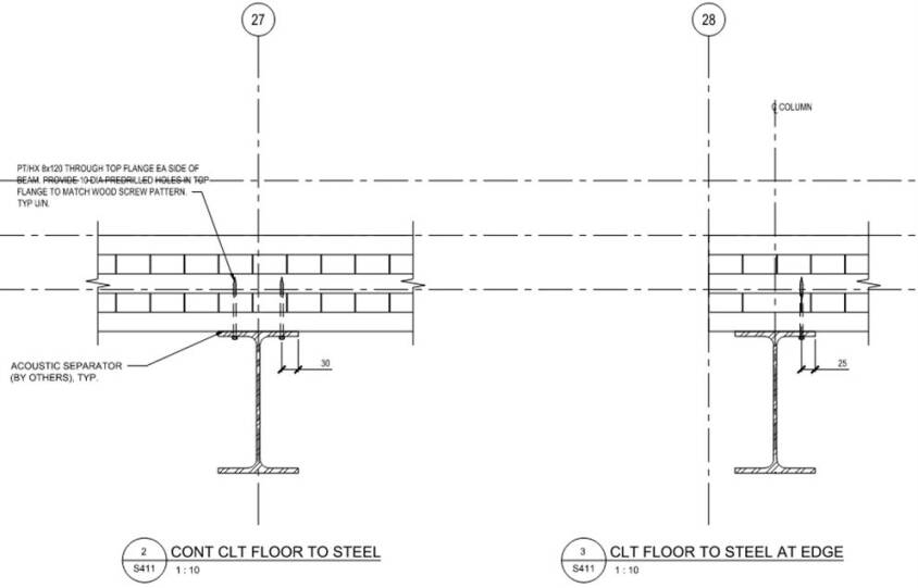
As with all mass timber construction, connection detailing is a critical component of the design, both between adjacent CLT panels and between the CLT panels and the structural steel elements. The following diagram illustrates two CLT-to-steel floor connection details. One for a continuous condition (left) and one at an edge condition (right)
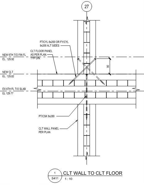
This diagram shows a vertical connection between a CLT wall panel and a CLT floor panel, illustrating how loads are transferred and how the two elements are joined.
Conclusion
The Pathway vertical addition demonstrates how mass timber can unlock new housing opportunities on existing sites, even within the constraints of aging concrete buildings. Through careful analysis, coordinated design, and close collaboration across the project team, the addition delivered high-quality, accessible homes with minimal disruption to residents and neighbours. As communities look to increase housing density responsibly and efficiently, this project offers a compelling model for how lightweight mass timber systems can extend the life and capacity of existing buildings while meeting today’s performance, sustainability, and speed-to-occupancy expectations.
Meeting Challenges Head On
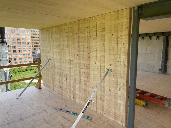
A strong working relationship with the full project team from the outset is essential to a successful outcome. For Pathways, this began with a detailed survey of the existing conditions and a shared understanding of the project’s risk tolerance. That early alignment set the foundation for a smooth installation process, allowing the walls and floors to be placed without issue.
Working with existing buildings often reveals unexpected conditions, and this project was no exception. After the cladding was removed from the shear wall, it became clear that the concrete surface was neither straight nor plumb. To accurately assess these irregularities, the contractor completed a 3D scan of the wall elevation to determine the actual tolerances.
Based on the scan, steel shim plates were installed behind the continuous HSS beam (ledger) on both floors. These shims filled the varying gaps between the new steel ledger and the uneven existing concrete wall, ensuring proper alignment and load transfer.
When the timber arrived on site, installation proceeded smoothly despite the tolerance differences between CLT and concrete. Concrete typically varies by 25–30 mm, while timber varies by only 2–3 mm, but the team was well prepared to accommodate these differences.
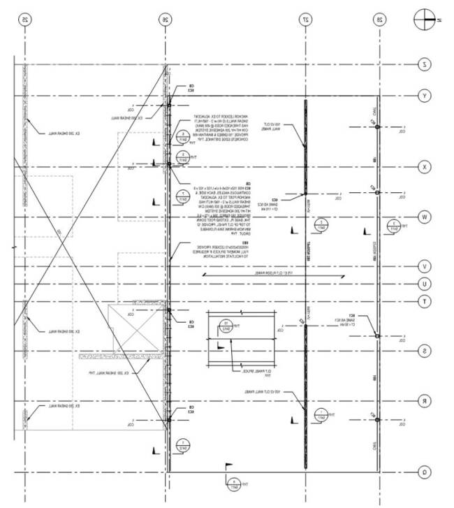
Lateral System
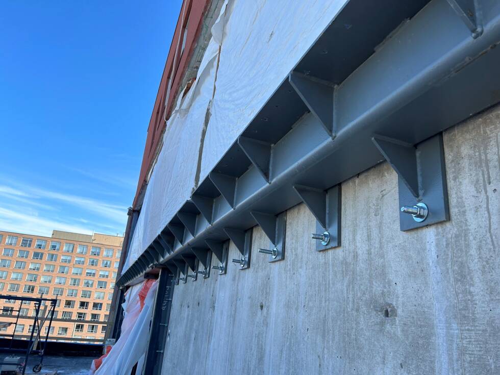
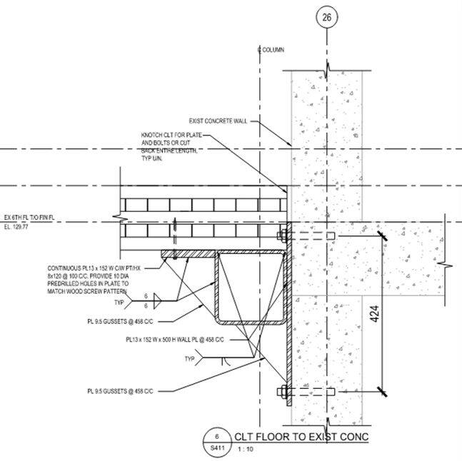
The existing building’s lateral system consists of concrete shear walls running in the building’s short direction. For the vertical addition, the CLT diaphragm is cantilevered beyond the last existing shear wall to reach the upper floors. A continuous HSS beam (ledger) and Hilti bolts are used to connect and anchor the new diaphragm to the existing shear wall.
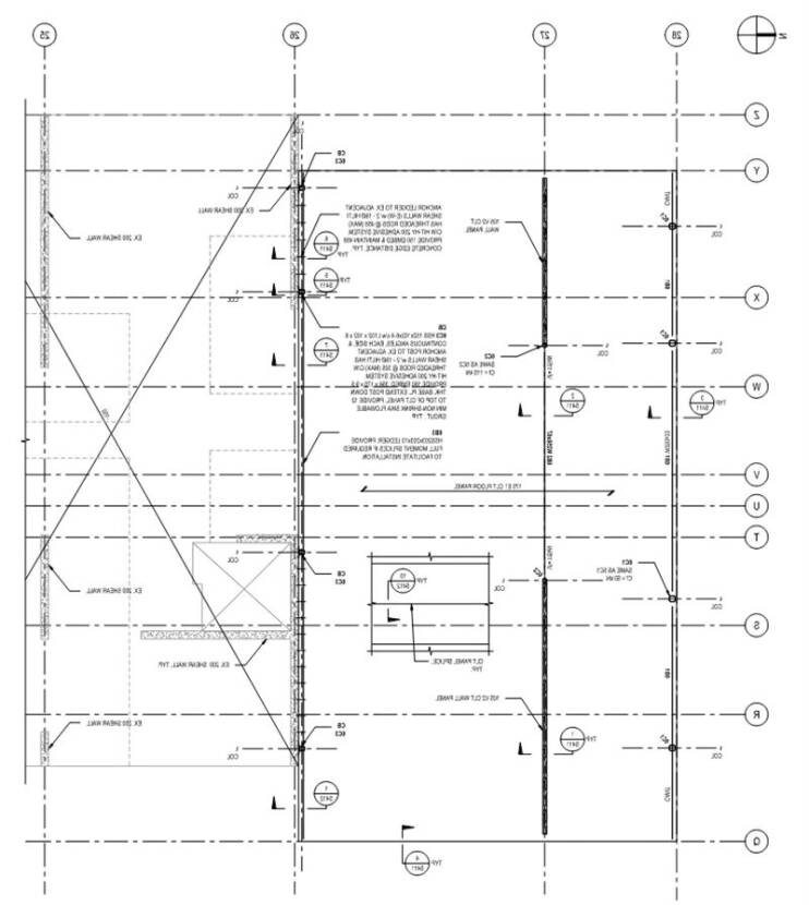
Framing Plan
This drawing shows the new sixth-floor framing plan. The two-span CLT floor panels, each 175 mm thick, run left to right (north–south) and extend across two residential units, spanning from steel beams at the outer perimeter, to the interior CLT demising walls, and then to the existing concrete structure. Using longer two-span panels reduced the total number of crane picks, improving assembly efficiency and speeding installation. The roof framing plan is similar to the sixth-floor framing plan.
Load Path and Structural Bays
Mass timber performs best in clear structural bays—simple rectangles or squares—rather than in irregular or tightly stacked configurations. It is most effective when columns run uninterrupted to the foundation, allowing loads to transfer straight down and simplifying both design and installation.
On this project, the team was able to take advantage of this structural logic by placing the new timber construction directly on top of the existing building’s structural bays. This ensured a clean and direct load path to the foundation without unnecessary complications.
Building materials | Construction thickness | Weight of system with Fire Rating |
Reinforced Concrete | 250mm | 6.0 kPa |
Structural steel frame with precast slabs | 200mm precast with 50mm topping | 5.0 kPa |
Structural steel frame with CLT panels/walls | 175mm | 3.0 kPa |
Structural steel frame with light gauge steel joists and USG concrete subfloor | 300 light gauge steel joists | 1.5 kPa |
Building material options | Floor system | Vertical system |
Reinforced concrete | Concrete flat slabs | Concrete columns |
Structural steel frames with precast slabs | Precast slabs with steel beams | Steel columns |
Structural steel frames with CLT panels/walls | CLT floor panels with steel beams | CLT wall panels with steel columns |
Structural steel frame with light gauge steel joists and USG concrete subfloor | Light gauge steel joists with steel beams | Steel columns |

Although CLT was not the lightest structural system considered, it remained significantly lighter than reinforced concrete and steel-precast alternatives, allowing it to meet the feasibility study’s weight-related design objectives.
In the proposed design, the floor and roof assemblies, as well as the interior structural walls, are constructed from CLT, with the remaining structural support provided by steel beams and columns. Because the required Alternative Solution for the building permit mandated non-combustible exterior walls, CLT could not be used for the exterior wall assemblies.
With mass timber identified as the most suitable lightweight system, the design team developed a structural strategy that addressed gravity loads, material interfaces, lateral stability, and construction practicalities.
Comparing the Options
The following chart compares four different structural systems:
reinforced concrete columns and slabs
steel frame with precast slabs
structural steel frame with CLT floor and wall panels
structural steel frame with light gauge steel joists and USG concrete subfloor
The following chart compares the weights of the four structural options considered:
The exterior Galvalume siding is mounted on Cascadia thermal clips over 4 in (≈102 mm) of Cavityrock exterior insulation, with 6 in (≈152 mm) of Comfortbatt in the interior walls. Each unit is served by an individual heat pump for heating and cooling, plus an energy recovery ventilarot (ERV). Energy modelling indicates the addition performs 7.1% better than MNECB 2020, slightly exceeding funder requirements.
All units are designed to barrier-free dimensions, with roll-in showers, and two include fully accessible kitchens. The wider door, corridor, and bathroom clearances contribute to a more spacious feel.
Structural Feasibility Study
In the beginning, a structural feasibility study that analyzed the building’s gravity and lateral systems was conducted to determine whether two floors could be added above the existing four-storey section.
The existing building was first modelled without the proposed addition to establish a baseline for analysis. It includes a single-storey parking garage beneath the full footprint and is supported by reinforced concrete footings. Both the vertical gravity and lateral systems, along with the reinforced concrete floor structures, were evaluated as part of the feasibility study. This assessment involved a combination of hand calculations and a detailed 3-D finite element model to analyze how the building’s gravity and lateral systems would perform.
The building was then re-modelled using the weights of various structural material options. This analysis showed that additional loading would range from approximately ±8% for the lightest option to ±20% for the heaviest. Based on these results, the existing structure was found capable of supporting a two-storey vertical addition—but only if a light to moderate construction material was used. A heavier structural system would exceed the building’s capacity and require reinforcement.
Mass timber panels were used for the central shear walls on both floors, the roof, and the sixth floor. Structural steel components were introduced to satisfy headroom and non-combustibility requirements. Tying the addition into the existing building both vertically and horizontally presented certain challenges, and the new construction had to be sprinklered in addition to the 5th and 6th floor corridors of the existing building.
Because permits were issued just before mass timber was adopted into the Ontario Building Code, the alternative solution required encapsulating all mass timber with gypsum wallboard (GWB). The 175 mm CLT floor was encapsulated with two layers of 16 mm GWB below, and topped with 50 mm of topping, 39 mm of Maxxon Acousti-Mat, and 5 mm of finished flooring above—resulting in a total thickness of approximately 300 mm.

Project Overview
Pathway Non-Profit Housing is an interfaith non-profit corporation that owns and operates two apartment buildings built in the early 1990s. By expanding their existing Arbour Mill property in Mississauga, they avoided the challenge of finding new land and were able to welcome new residents into an established, supportive community.
The resulting two-storey, 10m x 18m vertical addition at the north end of the building connects to the fifth and sixth floors of the adjacent seven-storey block, creating a cohesive addition without disrupting the building’s layout. Because the building remained occupied throughout, reducing construction time was a priority, a requirement that supported the choice of mass timber.
article en vedette
Vertical Addition Adds Essential Housing Units
PROJECT TEAM:
Regional Municipality of Peel
Rapid Housing Initiative
Pathway Non-Profit Community Developments Inc. of Peel (Pathway)
GSAI Planners
Tafler Rylett Architects
Engineering Link (Structural)
GPY & Associates Engineering Inc. (Mechanical)
Summit Engineering (Electrical)
Disano Sprinklers
Vortex Fire
HGC Acoustic Consultants
RDH Building Science
Scott Construction
Element5
Photos: Scott Construction Group, Derek Szczerbowski , CWC
Conclusion
The Pathway vertical addition demonstrates how mass timber can unlock new housing opportunities on existing sites, even within the constraints of aging concrete buildings. Through careful analysis, coordinated design, and close collaboration across the project team, the addition delivered high-quality, accessible homes with minimal disruption to residents and neighbours. As communities look to increase housing density responsibly and efficiently, this project offers a compelling model for how lightweight mass timber systems can extend the life and capacity of existing buildings while meeting today’s performance, sustainability, and speed-to-occupancy expectations.

Lateral System
The existing building’s lateral system consists of concrete shear walls running in the building’s short direction. For the vertical addition, the CLT diaphragm is cantilevered beyond the last existing shear wall to reach the upper floors. A continuous HSS beam (ledger) and Hilti bolts are used to connect and anchor the new diaphragm to the existing shear wall.
Framing Plan
This drawing shows the new sixth-floor framing plan. The two-span CLT floor panels, each 175 mm thick, run left to right (north–south) and extend across two residential units, spanning from steel beams at the outer perimeter, to the interior CLT demising walls, and then to the existing concrete structure. Using longer two-span panels reduced the total number of crane picks, improving assembly efficiency and speeding installation. The roof framing plan is similar to the sixth-floor framing plan.
Building material options | Floor system | Vertical system |
Reinforced concrete | Concrete flat slabs | Concrete columns |
Structural steel frames with precast slabs | Precast slabs with steel beams | Steel columns |
Structural steel frames with CLT panels/walls | CLT floor panels with steel beams | CLT wall panels with steel columns |
Structural steel frame with light gauge steel joists and USG concrete subfloor | Light gauge steel joists with steel beams | Steel columns |
Building materials | Construction thickness | Weight of system with Fire Rating |
Reinforced Concrete | 250mm | 6.0 kPa |
Structural steel frame with precast slabs | 200mm precast with 50mm topping | 5.0 kPa |
Structural steel frame with CLT panels/walls | 175mm | 3.0 kPa |
Structural steel frame with light gauge steel joists and USG concrete subfloor | 300 light gauge steel joists | 1.5 kPa |
Comparing the Options
The following chart compares four different structural systems:
reinforced concrete columns and slabs
steel frame with precast slabs
structural steel frame with CLT floor and wall panels
structural steel frame with light gauge steel joists and USG concrete subfloor
The following chart compares the weights of the four structural options considered:
Although CLT was not the lightest structural system considered, it remained significantly lighter than reinforced concrete and steel-precast alternatives, allowing it to meet the feasibility study’s weight-related design objectives.
In the proposed design, the floor and roof assemblies, as well as the interior structural walls, are constructed from CLT, with the remaining structural support provided by steel beams and columns. Because the required Alternative Solution for the building permit mandated non-combustible exterior walls, CLT could not be used for the exterior wall assemblies.
With mass timber identified as the most suitable lightweight system, the design team developed a structural strategy that addressed gravity loads, material interfaces, lateral stability, and construction practicalities.

The exterior Galvalume siding is mounted on Cascadia thermal clips over 4 in (≈102 mm) of Cavityrock exterior insulation, with 6 in (≈152 mm) of Comfortbatt in the interior walls. Each unit is served by an individual heat pump for heating and cooling, plus an energy recovery ventilarot (ERV). Energy modelling indicates the addition performs 7.1% better than MNECB 2020, slightly exceeding funder requirements.
All units are designed to barrier-free dimensions, with roll-in showers, and two include fully accessible kitchens. The wider door, corridor, and bathroom clearances contribute to a more spacious feel.
Structural Feasibility Study
In the beginning, a structural feasibility study that analyzed the building’s gravity and lateral systems was conducted to determine whether two floors could be added above the existing four-storey section.
The existing building was first modelled without the proposed addition to establish a baseline for analysis. It includes a single-storey parking garage beneath the full footprint and is supported by reinforced concrete footings. Both the vertical gravity and lateral systems, along with the reinforced concrete floor structures, were evaluated as part of the feasibility study. This assessment involved a combination of hand calculations and a detailed 3-D finite element model to analyze how the building’s gravity and lateral systems would perform.
The building was then re-modelled using the weights of various structural material options. This analysis showed that additional loading would range from approximately ±8% for the lightest option to ±20% for the heaviest. Based on these results, the existing structure was found capable of supporting a two-storey vertical addition—but only if a light to moderate construction material was used. A heavier structural system would exceed the building’s capacity and require reinforcement.
Mass timber panels were used for the central shear walls on both floors, the roof, and the sixth floor. Structural steel components were introduced to satisfy headroom and non-combustibility requirements. Tying the addition into the existing building both vertically and horizontally presented certain challenges, and the new construction had to be sprinklered in addition to the 5th and 6th floor corridors of the existing building.
Because permits were issued just before mass timber was adopted into the Ontario Building Code, the alternative solution required encapsulating all mass timber with gypsum wallboard (GWB). The 175 mm CLT floor was encapsulated with two layers of 16 mm GWB below, and topped with 50 mm of topping, 39 mm of Maxxon Acousti-Mat, and 5 mm of finished flooring above—resulting in a total thickness of approximately 300 mm.
Load Path and Structural Bays
Mass timber performs best in clear structural bays—simple rectangles or squares—rather than in irregular or tightly stacked configurations. It is most effective when columns run uninterrupted to the foundation, allowing loads to transfer straight down and simplifying both design and installation.
On this project, the team was able to take advantage of this structural logic by placing the new timber construction directly on top of the existing building’s structural bays. This ensured a clean and direct load path to the foundation without unnecessary complications.

Connections
As with all mass timber construction, connection detailing is a critical component of the design, both between adjacent CLT panels and between the CLT panels and the structural steel elements. The following diagram illustrates two CLT-to-steel floor connection details. One for a continuous condition (left) and one at an edge condition (right)
This diagram shows a vertical connection between a CLT wall panel and a CLT floor panel, illustrating how loads are transferred and how the two elements are joined.
Project Benefits
Sustainable Local Procurement: The CLT panels were fabricated at Element5’s FSC-certified facility in St. Thomas using wood sourced from sustainably managed Ontario forests, ensuring responsible practices from harvest to production.
Low-Carbon Construction: Using mass timber instead of steel reduced the structure’s embodied carbon by an estimated 20–50%. Its proximity to the manufacturing facility minimized transportation-related emissions and costs.
Lightweight Structural System: With a structural weight roughly 50% lower than an equivalent concrete building, the mass timber addition could be supported by the existing structure without the need for reinforcement.
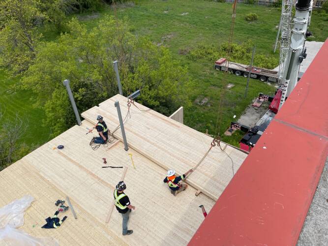
Cost-Effective, Rapid Construction: Mass timber construction is efficient and fast to assemble—typically 25% quicker than conventional methods, and in some cases even faster. For Pathway, close coordination of fabrication, delivery, and installation enabled the entire structure to be erected in just two and a half weeks. Full-length CLT floor panels and on-site drilling of mechanical penetrations further accelerated construction.
Quieter, Less Disruptive Site: Mass timber buildings are assembled rather than constructed on site, which significantly reduces noise and can cut construction-related vehicle traffic by up to 90%. Installation also requires fewer workers; at Pathway, the mass timber was erected by a crane operator and a small crew of two to three people, minimizing disruption to the surrounding neighbourhood.
Gentle Densification: Expanding the existing site avoided impacts on adjacent properties and allowed new residents to integrate immediately into an established community with familiar supports already in place.
Meeting Challenges Head On
A strong working relationship with the full project team from the outset is essential to a successful outcome. For Pathways, this began with a detailed survey of the existing conditions and a shared understanding of the project’s risk tolerance. That early alignment set the foundation for a smooth installation process, allowing the walls and floors to be placed without issue.
Working with existing buildings often reveals unexpected conditions, and this project was no exception. After the cladding was removed from the shear wall, it became clear that the concrete surface was neither straight nor plumb. To accurately assess these irregularities, the contractor completed a 3D scan of the wall elevation to determine the actual tolerances.
Based on the scan, steel shim plates were installed behind the continuous HSS beam (ledger) on both floors. These shims filled the varying gaps between the new steel ledger and the uneven existing concrete wall, ensuring proper alignment and load transfer.
When the timber arrived on site, installation proceeded smoothly despite the tolerance differences between CLT and concrete. Concrete typically varies by 25–30 mm, while timber varies by only 2–3 mm, but the team was well prepared to accommodate these differences.